#5 volt dc motors arduino driver#
The motor we’ll control is connected to the motor A output pins, so we need to wire the ENABLEA, INPUT1 and INPUT2 pins of the motor driver to the ESP32.

#5 volt dc motors arduino how to#
Now that you know how to control a DC motor with the L298N motor driver, let’s build a simple example to control the speed and direction of one DC motor. Recommended reading: Build Robot Car Chassis Kit for ESP32, ESP8266, Arduino, etc… Control DC Motor with ESP32 – Speed and Direction The following table shows the input pins’ state combinations for the robot directions. For example, to make the robot turn right, enable the motor at the left, and disable the motor at the right. To turn the robot in one direction, you need to spin the opposite motor faster. To make it go backwards, both should be rotating backwards. If you want to build a robot car using 2 DC motors, these should be rotating in specific directions to make the robot go left, right, forward or backwards.įor example, if you want your robot to move forward, both motors should be rotating forward. Motor B can be controlled using the same method but applying HIGH or LOW to input 3 and input 4.Ĭontrolling 2 DC Motors – ideal to build a robot

Jumper: jumper in place – uses the motors power supply to power up the chip.Acts as a 5V output if jumper is in place

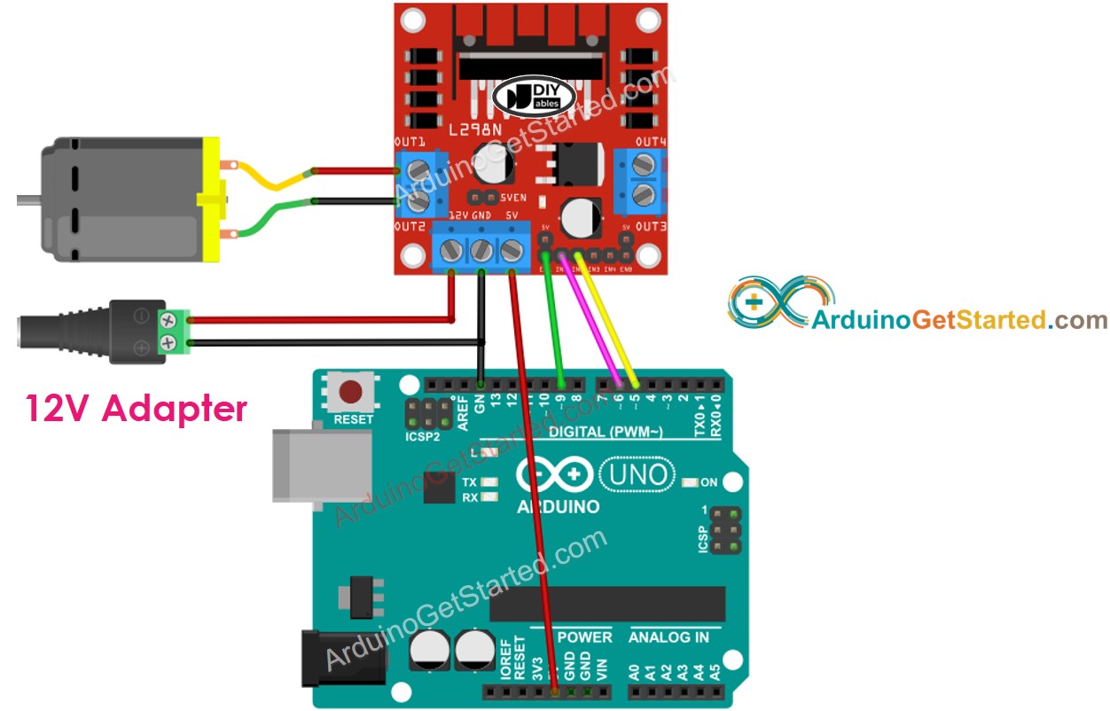
+12V: The +12V terminal is where you should connect your power supply.For example, you can use a bench power supply to test this tutorial. In this tutorial will be using 4 AA 1.5V batteries that combined output approximately 6V, but you can use any other suitable power supply. It’s important to note that despite the +12V terminal name, with the setup we’ll use here (with the jumper in place) you can supply any voltage between 6V and 12V. Note: if you supply more than 12V, you need to remove the jumper and supply 5V to the +5V terminal. However, if the jumper is in place, the chip is powered using the motor’s power supply and you don’t need to supply 5V through the +5V terminal. The +5V terminal is used to power up the L298N chip. The +12V terminal block is used to power up the motors. OUT1 and OUT2 at the left and OUT3 and OUT4 at the right.Īt the bottom you have a three terminal block with +12V, GND, and +5V. The motor driver has a two terminal block in each side for each motor.


 0 kommentar(er)
